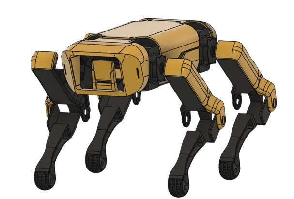
Spot Micro
UNDER DEVELOPMENT
"Simulation-First Quadruped Robotics — ROS 2 Digital Twin, SLAM/Navigation, and Reinforcement Learning for Locomotion"
Spot Micro is a research-oriented quadruped platform built with a simulation-first methodology. Our core goal is to develop a high-fidelity digital twin (URDF/Xacro + physics) and a disciplined ROS 2 software stack, then leverage reinforcement learning (RL) to optimize locomotion policies in simulation before transferring them safely to real hardware. The roadmap is structured around three pillars: (1) accurate simulation and reproducible experiments, (2) ROS 2 integration for modular robotics software, and (3) AI/RL for improving stability, tracking, and efficiency under real-world constraints.
- Platform: 12-DoF quadruped (3D-printed)
- Compute: Raspberry Pi 5 (8GB)
- Actuation: 12× MG996R + PCA9685
- Sensing: MPU-6050 IMU (LiDAR planned)
- Core Focus: Simulation • ROS 2 • RL Locomotion
Executive Summary
This project presents a cost-efficient quadruped robot platform designed for AI-driven robotics research with strong emphasis on simulation accuracy and reproducibility. The system is developed in stages: first validating safe actuation and stable basic motion, then building a CAD-matched URDF/Xacro digital twin for ROS 2 integration and simulation benchmarking. With a reliable simulation baseline, the project introduces SLAM and navigation using LiDAR within ROS 2, and finally applies reinforcement learning to optimize locomotion behavior while reducing simulation-to-real mismatch through careful modeling and staged deployment.
Problem Statement
Quadruped robots can operate in complex terrain and confined environments, but they require coordinated multi-joint control, stability under dynamic motion, and careful deployment practices. Advanced autonomy and learning-based control often face the simulation-to-real gap, and many commercial platforms are expensive. This project addresses these constraints by prioritizing an accurate digital twin, ROS 2 modularity, and a simulation-first RL workflow that enables repeatable evaluation before real hardware deployment.
Research Question
How can we build a cost-efficient quadruped platform where a high-fidelity simulation and ROS 2 digital twin enable reproducible locomotion experiments, SLAM/navigation integration, and reinforcement learning policy optimization, while minimizing simulation-to-real error for safe and reliable deployment on physical hardware?
Related Work (status)
The project aligns with modern research in simulation-based robotics development, ROS 2 modular architectures, SLAM/navigation pipelines, and reinforcement learning for locomotion. The team has initiated a focused literature review and is actively reading multiple research papers spanning these domains. Because the work intersects simulation fidelity, ROS 2 integration, SLAM, and RL locomotion, we synthesize insights across multiple publications to justify design choices and position the project within the state of the art.
Project Objectives
Core Objectives (Phase 1)
- Establish a stable simulation baseline and a reproducible experiment setup (configs, logs, versioned assets).
- Servo bring-up, calibration, and safe standing posture (Stand) aligned with simulation joint limits.
- Implement inverse kinematics per leg and execute joystick/controller commands as a controlled baseline.
- Implement a stable initial gait (Crawl) and achieve repeatable walking trials.
- Use IMU feedback for basic posture and stability compensation (pitch/roll).
Advanced Objectives (Phases 2–4)
- Build a CAD-matched URDF/Xacro digital twin to support ROS 2 visualization, TF correctness, and simulation benchmarking.
- Integrate with ROS 2 (nodes, topics, TF, RViz) for modular control and testing workflows.
- Add LiDAR and perform SLAM/mapping, then navigation with obstacle avoidance (Nav2).
- Train and deploy reinforcement learning locomotion policies: simulation training first, then staged real transfer with safety constraints.
Methodology & Simulation-First Development Path
The methodology is simulation-first: we treat the digital twin as the foundation for reproducible testing, controller benchmarking, and RL training. Hardware experiments are introduced gradually and only after simulation baselines are validated. This reduces risk, improves safety, and supports repeatable scientific evaluation across design, simulation, deployment, and validation.
Mechanical Design & 3D Printing
The chassis and leg structures are designed as a complete CAD assembly and manufactured using 3D printing for rapid iteration. CAD is treated as the single source of truth to ensure link dimensions and joint placements match the URDF/Xacro model, directly improving simulation fidelity and ROS 2 consistency.
Key Dimensions (Reference + CAD Finalization)
Because the mechanical layout follows the SpotMicro family closely, this proposal includes widely adopted open-source reference dimensions for core body size and leg link lengths. The final envelope (overall L/W/H) will be confirmed from Fusion 360 using Inspect → Measure prior to fabrication and URDF export.
| Parameter | Symbol | Value (mm) |
|---|---|---|
| Body length (chassis only) | Lb | 207.5 |
| Body width (chassis only) | Wb | 78.0 |
| Coxa (hip) link length | l0 | 60.5 |
| Hip-to-knee link length (femur) | l1 | 111.2 |
| Knee-to-foot link length (tibia) | l2 | 118.5 |
| Max leg reach | Rmax | 219.7 |
| Body height range (IK feasible) | Hb | 98.9–197.7 |
Final dimensions will be locked from Fusion 360 prior to fabrication and URDF export.
Power, Safety, and Real-World Constraints
Real hardware introduces strict constraints: current draw, voltage drops, servo backlash, and mechanical stress. Power integrity is treated as a first-class requirement, using a dedicated high-current 5V servo rail separate from the Raspberry Pi supply with a common ground. Software safety limits (joint limits, soft-start, conservative gait timing) protect hardware during early experiments and staged policy deployment.
Baseline Control (IK + Joystick) for Benchmarking
The baseline controller is intentionally simple and measurable: inverse kinematics converts desired foot targets into joint angles, while a conservative gait generator (Crawl) provides stable stepping. Joystick teleoperation is used as a controlled input source to benchmark stability and tracking in both simulation and real hardware, forming the foundation for later ROS 2 integration and RL optimization.
Digital Twin & ROS 2 Modeling (URDF/Xacro)
A CAD-matched URDF/Xacro model is created to serve as a digital twin. Joint limits, coordinate frames, and inertial approximations are aligned to the physical robot so that TF trees and RViz visualization remain consistent. This digital twin enables simulation benchmarking, faster debugging, and reproducible experiments, and it reduces sim-to-real mismatch before RL policies are deployed.
ROS 2 Integration (Modular Robotics Software)
ROS 2 is used to structure the software stack into modular components: control nodes, sensor interfaces, TF publishers, RViz visualization, and test tools. By standardizing the pipeline in ROS 2, the project supports repeatable validation, easier collaboration, and clean transitions from simulation to real hardware.
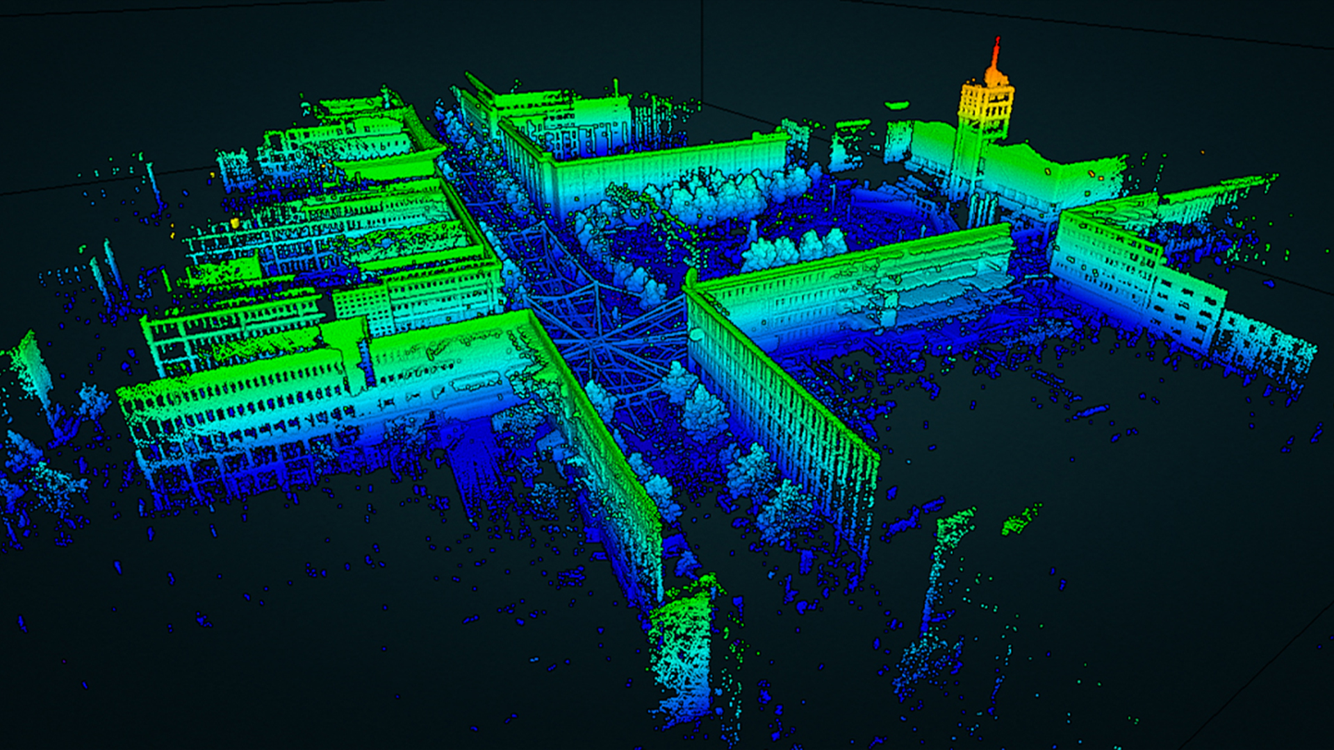
SLAM & Navigation (LiDAR + Nav2)
With a correct ROS 2 model and TF setup, LiDAR-based SLAM is introduced to produce a 2D occupancy grid map. The navigation stage uses ROS 2 Nav2 to reach goal poses and avoid obstacles using costmaps and local planning. The process is incremental: teleop mapping first, then navigation tuning and robustness tests.
Reinforcement Learning for Locomotion (Simulation → Real)
Reinforcement learning is used as an optimization layer for locomotion rather than raw servo-level control. Policies optimize gait parameters (step length, step height, timing, posture offsets) and stability objectives. Training begins in simulation using the digital twin, supported by domain randomization (noise, friction, mass variations) to reduce sim-to-real gap. Deployment to hardware is staged with conservative limits and strict safety constraints.
System Components (Current Build)
- Raspberry Pi 5 (8GB) with active cooler
- microSD Card (64GB, Class 10)
- 12x MG996R metal gear servo motors
- PCA9685 16-channel I2C servo driver
- MPU-6050 (GY-521) IMU module
- Raspberry Pi Camera Module (v2 or v3)
- OLED SSD1306 (128x64, I2C)
- LED power button and rocker power switch
- 7.4V (2S) Li-Po battery
- DC-DC buck converter (5V, >= 5A)
- Mechanical hardware: bearings (F625zz), screws/nuts (M3/M4/M5)
Planned addition:
- 2D LiDAR sensor (required for SLAM and navigation).
Technical Architecture (High-Level)
Simulation & Digital Twin: URDF/Xacro + physics simulation used for benchmarking and RL training. Actuation: PCA9685 PWM output to servos. Kinematics: IK transforms foot trajectories into joint angles. Gait planning: Crawl baseline with conservative timing. Stability: IMU-based posture compensation (pitch/roll). ROS 2 layer: nodes, topics, TF, RViz, Nav2. Perception: LiDAR (SLAM) and camera (optional). Learning: RL policies optimize locomotion parameters for stability and efficiency.
Early-Phase Acceptance Criteria
To ensure objective evaluation, early milestones are defined with measurable pass/fail criteria:
- ROS 2 readiness: URDF/Xacro visualizes correct joint motion in RViz and TF frames are consistent.
- Walk (Crawl): walk forward for ≥ 3 meters under joystick control with at least 2 repeatable successful trials.
- Stand: maintain a stable standing posture for ≥ 60 seconds without a fall and without violating joint limits.
Roadmap & Timeline Estimates
The following timeline estimates assume 1-2 hours of work per day. With more time, durations shrink proportionally.
| Stage | Scope and Deliverable | Estimated Duration |
|---|---|---|
| Stage 0 | Simulation baseline + power and wiring validation | 3-7 days |
| Stage 1 | Mechanical assembly (mount servos, bearings, chassis, cable management) | 7-14 days |
| Stage 2 | Servo bring-up, calibration, Stand posture | 7-14 days |
| Stage 3 | IK + joystick teleoperation (baseline benchmarking) | 14-21 days |
| Stage 4 | Crawl gait + IMU compensation (repeatable walk trials) | 14-28 days |
| Stage 5 | URDF/Xacro digital twin (RViz + TF correctness) | 7-14 days |
| Stage 6 | ROS 2 integration (nodes, topics, testing pipeline) | 14-21 days |
| Stage 7 | LiDAR SLAM/mapping (produce and save a 2D map) | 14-28 days |
| Stage 8 | Navigation + obstacle avoidance (Nav2 tuning, go-to-goal) | 21-42 days |
| Stage 9 | RL locomotion optimization (sim training → staged real transfer) | 28-56 days |
Risk Management (Key Risks and Mitigations)
- Simulation-to-real gap: CAD-matched digital twin, domain randomization, staged deployment with strict safety constraints.
- High current draw / voltage drop: Dedicated high-current 5V servo buck, separate from Pi; common ground; soft-start.
- Servo inaccuracy/backlash: Crawl baseline first, calibration, joint limits, conservative timing.
- SLAM and TF inconsistencies: Accurate URDF/Xacro frames, validate TF tree in RViz, teleop mapping first.
- Mechanical stress: reinforce mounts, iterate prints at high-stress points, reduce sudden motions.